Synthesis State-machines from a communication diagram †
Its procedure is as follows:
Example †
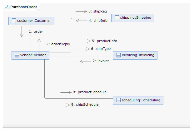
The example choreography is shown right. The figure is a collaboration diagram of UML1.x. *1
The example is a modified version of a collaboration by T. Bultan and X. Fu, which is taken from BPEL-WS 2.0 specification.
This example is composed of five services: Customer, Vendor, Shipping, Invoicing, and Scheduling. When Vendor receives an order from Customer, it sends requests to Shipping, Invoicing and Scheduling. Finally, Vendor returns orderReply to Customer.
The request to Shipping is shipReq, and the reply from Shipping is shipInfo.
The requests to Invoicing are productInfo and shipType; the reply from Invoicing is invoice. Vendor sends productInfo after receiving order; it sends shipType after receiving shipInfo. Invoicing does internal process to make an invoice after receiving productInfo and shipType; then it sends invoice as a reply.
The request to Scheduling are productSchedule and shipSchedule. Vendor sends productSchedule after receiving order; it sends shipSchedule after receiving shipInfo.
Vendor sends orderReply to Customer after receiving shipInfo and invoice and sending shipSchedule.
Draw Class Diagram †
Create an UML project in RSA.
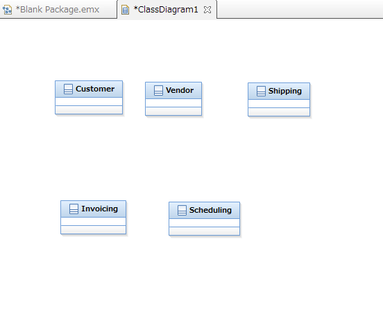
Add new class diagram; create classes for the services: Customer, Vendor, Shipping, Invoicing, and Scheduling.
Draw Communication Diagram †
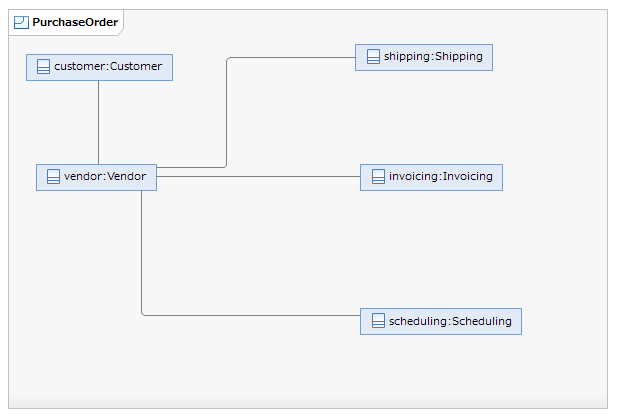
Add new communication diagram; place all classes as lifelines.
Draw message pathways between lifelines that communicates.
Add messages.
RSA has three message types:
- Asynchronous Call
- Asynchronous Signal
- Synchronous Call
CSCB Tools supports two of them: Asynchronous and Synchronous Calls. In this example, we assume that all messages are asynchronous calls. The communication diagram added messages is shown below.
Define ordering relation among messages.
- Communication diagrams does not have predecessors, which collaboration diagrams have.
- The ordering relation of the example cannot be represented by the sequence number.
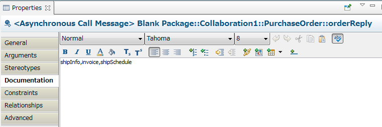
In CSCB Tools, we specify the preceding messages in the "Documentation". For example, because shipInfo, invoice, and shipSchedule precede orderReply, we add them in the Documentation of orderReply as below.
Now, it is ready to synthesize state machines.
synthesis state-machine †
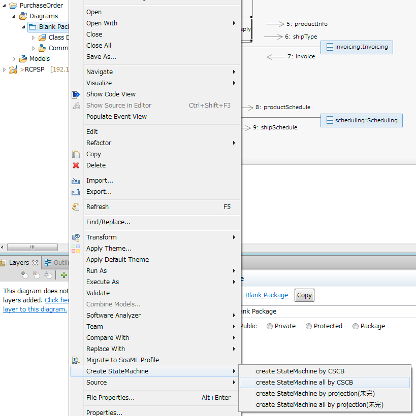
Right click the package in Project Explorer and select "Create StateMachine?" -> "create State Machine all by CSCB" from the menu; then a state machine for each service is synthesized.
By the way, if "create State Machine by CSCB" is selected, one can select a service to be synthesized. If "... by projection" is selected, state machines are synthesized by the projection method.
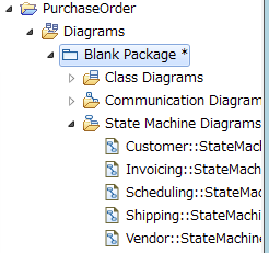
When there is no problem, state machines are synthesized and added to the model. The Blank Package of PurchaseOrder?; project in the above diagram has only Class Diagrams and Communication Diagrams; now it has State Machine Diagrams as shown below.
Results †
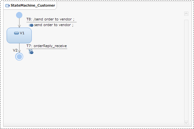
- Customer state machine
Customer executes the effect "send order to vendor", i.e. sends message order to vendor, at the transition from initial pseudo state to V1; it transitions to final state by the occurrence of the event orderReply_receive, i.e. receives message orderReply.
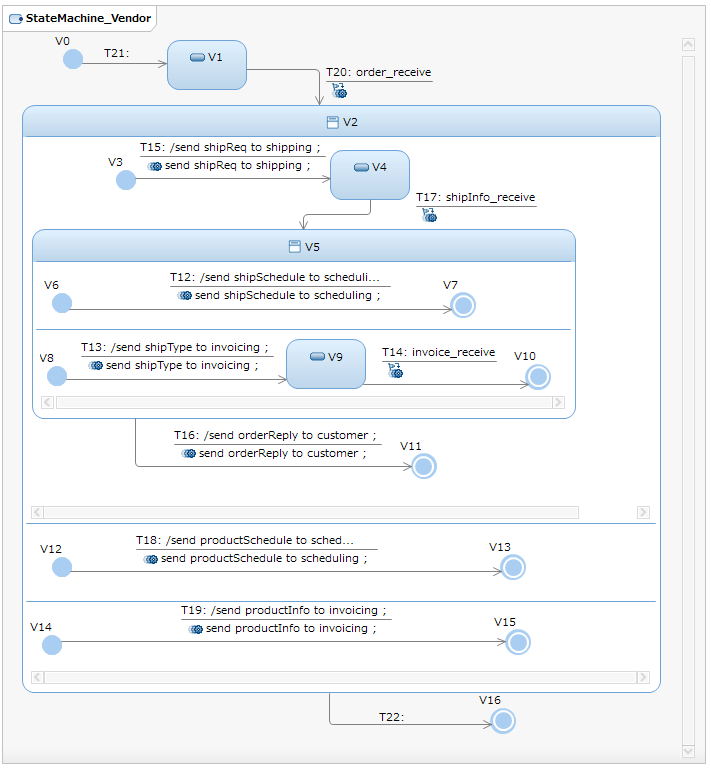
- Vendor state machine
When vendor receives order, three processes run concurrently; these processes are represented the state machines in the three regions of the composite state V2.
In the first region, vendor sends shipReq to shipping, and receives shipInfo. Then, the process forks into two processes. In the first process, vendor sends shipSchedule to scheduling; in the another process, it sends shipType to invoicing and receives invoice. Vendor sends &color(blue){orderReply} to customer when two processes terminate.
In the second region, vendor sends productSchedule to scheduling.
In the third region, vendor sends productInfo to invoicing.
When all processes in the three regions terminate, vendor transitions to the final state.
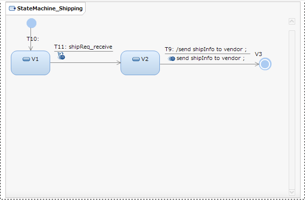
- Shipping state machine
Shipping received shipReq, and then sends shipInfo to vendor.
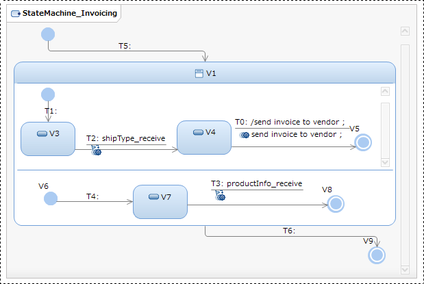
- Invoicing state machine
Invoicing receives shipType and productInfo concurrently; then it sends invoice to vendor after receiving shipType. *2
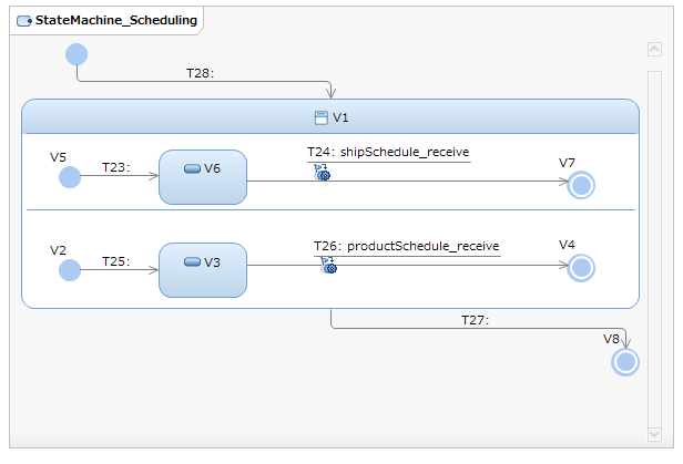
- Scheduling state machine
Scheduling receives shipSchedule and productSchedule.
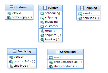
- Class diagram
The class diagram is updated as below, where references to communicating partners and called methods are added.

